How BIM to BIM Studio Aligns with Global BIM Standards

BIM to BIM Studio delivers globally aligned BIM solutions for smart, scalable, and standards-compliant construction

If you’re involved in the architecture, engineering, or construction industry, you’ve probably heard the term global BIM standards thrown around. But what do they really mean for you? Why should you care? Let me explain. These standards aren’t just technical jargon, they’re the secret sauce behind smooth, efficient building projects worldwide. Without them, managing tons of data, coordinating teams, and keeping everything on track would be a nightmare. So, what’s the big deal? Here’s the thing: at BIM to BIM Studio, we don’t just deliver BIM services, we make sure everything we do follows the best global BIM standards. Why? Because that’s how we guarantee quality, consistency, and collaboration across your entire project lifecycle. Think about it: when your project aligns with international BIM guidelines and buildingSMART standards, you get seamless data flow, fewer mistakes, and faster decision-making. It means your team can work better together, whether they’re using Revit standards, managing BIM workflows, or coordinating with subcontractors. Now, you might be wondering, how exactly does BIM to BIM Studio make all this happen? In this blog, I’ll show you how we integrate global BIM standards into everything we do, from BIM implementation to project delivery—so you get the best results every time. Ready to dive in? Let’s get started. Global BIM Standards Firstly, what exactly are global BIM standards? Simply put, these are agreed-upon rules, guidelines, and best practices that govern how Building Information Modeling (BIM) is carried out across different countries and projects. Think of them as a universal language for BIM, ensuring that everyone, from architects and engineers to contractors and facility managers—is on the same page. You might ask, why do these standards matter so much? Well, without a common framework, collaboration can quickly become chaotic. Imagine trying to fit puzzle pieces together when each piece is made differently. That’s why these standards exist: to create BIM modeling consistency and smooth collaboration across the entire AEC industry. Some of the most widely recognized standards include the buildingSMART standards, which focus on interoperability—making sure different BIM software like Revit, Navisworks, or Civil 3D can exchange information without losing crucial details. Then you have national BIM standards like those from the UK or the US, which set specific requirements for project teams to follow. At BIM to BIM Studio, we stay fully updated with these standards. Why? Because compliance means your projects meet global expectations for quality and efficiency. It also means we can handle everything from a BIM execution plan to managing the common data environment without a hitch. In short, adhering to global BIM standards is not just about ticking boxes—it’s about ensuring that your project information flows smoothly, your teams stay coordinated, and your building design processes meet the highest benchmarks worldwide. Want to know how this translates into your project? Keep reading—we’ll break down exactly how BIM to BIM Studio aligns with these standards every step of the way. BIM Standards Compliance So, what does BIM standards compliance really mean? At its core, it’s about following a defined set of protocols to ensure your BIM processes are accurate, efficient, and aligned with international expectations. It’s not just about using the right software it’s about using it the right way. Compliance ensures that your models are structured, your data is clean, and your documentation meets both local and global requirements. Without this alignment, your BIM models may become unusable for partners, clients, or regulatory bodies. At BIM to BIM Studio, compliance is not an afterthought, it’s a built-in part of our workflow. We meticulously follow guidelines laid out by leading standards bodies, including: ISO 19650 for managing information over the lifecycle of a built asset using BIM. buildingSMART’s IFC standards for interoperability across different platforms and disciplines. Revit modeling standards that ensure consistency in families, naming conventions, parameters, and levels of detail. We regularly conduct internal audits to keep our workflows compliant. Our team of experienced BIM coordinators ensures that every file, every model, and every output meets required benchmarks before it reaches you. Why is this so important? Because when your project complies with standards, you avoid costly miscommunication, improve stakeholder collaboration, and make your models future-ready—whether for construction, facility management, or renovation years down the line. With BIM to BIM Studio by your side, you’re not just meeting BIM standards—you’re exceeding them. BIM Implementation Let’s take a closer look at how global BIM standards move from paper to practice. This step is known as BIM implementation where the real transformation begins. It’s not just about using software like Revit or Navisworks; it’s about building a solid process that supports consistent collaboration, quality deliverables, and informed decision-making throughout a project’s lifecycle. At BIM to BIM Studio, we believe successful implementation starts with clarity and planning. First, we assess your current workflows, project requirements, and digital maturity. Then, we craft a detailed BIM Execution Plan (BEP) aligned with global frameworks like ISO 19650 or the National BIM Standard (NBIMS-US). This plan outlines how models will be created, shared, and updated—ensuring every stakeholder knows what to expect and when. But that’s just the beginning. Our team standardizes your modeling practices, sets up templates, and ensures naming conventions, file formats, and model structures follow international BIM guidelines. From 3D model setup and clash detection to quantity takeoffs and scheduling (4D/5D BIM), we make sure the entire process flows smoothly. And here’s what makes us different: we don’t leave you halfway. Our support continues throughout the project and beyond. With BIM to BIM Studio, you’re not just implementing a tool—you’re embracing a smarter way to build, collaborate, and manage. Project Delivery Here’s something that often gets overlooked in BIM conversations— How your project is delivered matters just as much as how it’s designed. At BIM to BIM Studio, we don’t just focus on modeling; we focus on end-to-end project delivery that aligns with global BIM standards every step of the way. What Does Project Delivery Really Mean in BIM? In the world of Building Information Modeling, project … Read more

The 7 Stages of the BIM Lifecycle Management

Illustration showing different stages of the BIM lifecycle from digital design and planning on a computer

Have you ever thought about what happens to a building after it’s completed? The truth is, a building goes through many stages, starting long before construction begins and continuing long after people move in. That entire journey is managed through something called BIM Lifecycle Management, or BLM. So, what does that mean for you? bim lifecycle management is the process of overseeing a building from the first idea to its final day of use. It includes everything from early planning and design to construction, facility operations, maintenance, and even demolition. Each phase is connected, and each decision can impact the building’s performance, cost, and sustainability. In today’s construction industry, BLM helps teams to work smarter and reduce mistakes. And with digital tools like Building Information Modeling (BIM), it’s easier than ever to manage every part of the building’s life in one place. In this blog, I’ll guide you through each major phase of the building lifecycle—and show how you can use BLM and BIM together to get better results. 1. Pre-design Phase: Before any sketches are made or models are built, there’s an essential step that sets everything in motion: the pre-design phase. This is where ideas take shape. It’s the point where questions are asked, goals are defined, and key decisions are made. What type of building is needed? Who will use it? What is the budget? What does the site offer or limit? During this phase, you’ll typically focus on: Understanding client needs— What are the expectations and requirements for the space? Site analysis— looking at location, zoning laws, access, climate, and potential challenges. Initial budget and schedule estimates— making sure the project is financially and logistically feasible. Project scope definition— deciding the size, function, and key features of the building. Team building— bringing together architects, consultants, and other professionals. Why is this phase so important? Because every decision made here will affect the outcome later. A strong pre-design phase prevents misunderstandings, cost overruns, and project delays. It sets a clear vision and makes sure the entire team is working toward the same goal. 2. Design Phase: Now that the goals and requirements are clear, it’s time to bring the concept to life. This is where the design phase begins and it’s one of the most collaborative stages in the entire building lifecycle. So, what actually happens here? This is the stage where architects, engineers, and consultants work together to transform the project brief into detailed drawings and digital models. It’s more than just pretty sketches. Every wall, window, material, and system gets carefully planned. Here’s what the design phase typically includes: Schematic Design: This is the early design draft. It outlines the basic layout, space planning, and visual direction of the building. Design Development: More details are added. Structural systems, HVAC, lighting, materials, and dimensions are specified. Construction Documents: Final technical drawings and specifications are prepared. These are the instructions contractors will follow on-site. Why is this phase so important? At this point, tools like Building Information Modeling (BIM) start to shine. BIM allows the entire team to work on a shared 3D model, improving coordination and catching issues before construction even begins. This phase is all about making choices with clarity, precision, and collaboration. 3. Construction Phase: The plans are in place. The drawings are approved. Now it’s time to break the ground. The construction phase is where everything starts to take physical form. But it’s more than just bricks and concrete; it’s a highly coordinated process that requires constant communication, decision-making, and problem-solving. Here’s what typically happens during this phase: Site preparation—clearing land, grading, and laying the foundation. Structures and systems built with walls, roofs, electrical, plumbing, HVAC, and more. Inspections and quality checks happen at each stage to ensure everything meets code and safety standards Why is this phase so important? Because mistakes here can be costly and hard to fix. That’s why construction teams rely on precise schedules, real-time updates, and technology tools to keep things on track. This is also where BIM continues to prove its value. With 3D models accessible on-site, teams can visualize each step, resolve clashes early, and coordinate across trades much more efficiently. Once construction is complete and the building is inspected and approved, it’s handed over for its next life stage: facility management. 4. Facility Management: Just because the building is finished doesn’t mean the job is over. In fact, this is where BIM lifecycle management continues to prove its worth through the long-term operation and maintenance of the building. Welcome to the facility management phase. So, what happens during this stage? This phase focuses on everything required to keep the building functional, safe, and efficient over time. It includes managing day-to-day operations, ensuring comfort for occupants, and addressing wear and tear as the building ages. Key responsibilities include: Monitoring building systems like HVAC, lighting, plumbing, and electrical for performance and efficiency Routine maintenance and repairs to prevent breakdowns or extend equipment life Space management to optimize how the building is used Asset tracking—keeping records of equipment, warranties, and service history Energy and cost control through smart monitoring and automation systems Why is this phase so important? With a digital model containing all the building’s data—materials, systems, layouts—facility managers can access what they need instantly, saving time and reducing maintenance costs. No more digging through paper files or outdated blueprints. And with the rise of smart buildings, this phase is getting more advanced, using sensors, analytics, and automation to keep buildings healthier and more sustainable. 5. Sustainability: Here’s a simple truth: buildings aren’t just structures; they’re long-term investments in people and the planet. And that’s exactly where sustainability enters the picture. In today’s world, sustainable construction is no longer optional. It’s becoming a standard. Why? Because buildings account for a significant portion of global energy use, carbon emissions, and resource consumption. So, what does sustainable construction actually involve? Energy efficiency: Designing buildings that use less power through smart insulation, efficient lighting, and HVAC systems. Sustainable materials: … Read more

Preconstruction Meeting: Avoid Costly Mistakes Before You Build

Preconstruction meeting setup showing how to reduce cost in construction project with planning and coordination.

Most construction projects don’t fail because of what happens on-site; they fail because of what wasn’t discussed before the site was even active. That’s why a preconstruction meeting is not just a formality; it’s a necessity. Think of it as your project’s launchpad. It’s where stakeholders, contractors, architects, and project managers come together to get on the same page before any work begins. From scope clarification and timeline expectations to safety procedures and responsibilities, this meeting sets the tone for the entire project. Without it, you’re walking into construction blind, leaving room for miscommunication, delays, rework, and budget overruns. But when done right, a preconstruction meeting helps you catch issues early, align everyone’s expectations, and create a smoother, more predictable path forward. In this blog, we’ll break down exactly what a preconstruction meeting is, why it’s crucial, who needs to be in the room, and what kind of outcomes you should expect by the end of it. If you’re looking to reduce costly mistakes and boost your project’s success rate, this is the first step What is a preconstruction meeting? A preconstruction meeting is a formal gathering held before the actual construction work begins. It serves as the kickoff meeting where key project stakeholders like the owner, general contractor, subcontractors, architect, and project manager come together to discuss every major aspect of the project. This meeting isn’t just about introductions. It’s about setting expectations, clarifying roles, reviewing the project scope, and laying down the ground rules for how the construction process will unfold. It covers everything from construction schedules, communication protocols, change order processes, and safety guidelines to risk management strategies. Essentially, it’s the roadmap that guides your team from groundbreaking to project delivery. Whether it’s a commercial high-rise, a custom home, or a renovation job, the preconstruction meeting ensures everyone is aligned before the first hammer swings. Why Are Preconstruction Meetings Important? Let’s be real, construction projects are complex. Without clear communication upfront, small misunderstandings can snowball into expensive delays, design errors, and costly rework. That’s where the preconstruction meeting becomes a game-changer. This meeting brings everyone involved in the construction project (from architects and engineers to contractors and clients) together to get on the same page before the first shovel hits the ground. It’s the best opportunity to align expectations, prevent issues, and lay the groundwork for a smooth construction process. Let’s break down exactly why preconstruction meetings are so important: 1. Reduces Miscommunication One of the biggest causes of project failure is poor communication. A preconstruction meeting helps ensure that every stakeholder understands the project scope, schedule, deliverables, and responsibilities. Misaligned expectations are cleared up early, so everyone knows what to do and when to do it, avoiding confusion on-site later. 2. Prevents Delays Delays often happen when problems aren’t discovered until it’s too late. Whether it’s a permit that wasn’t pulled or a misinterpreted blueprint, these issues can grind progress to a halt. Preconstruction meetings give you the chance to review logistics, permits, scheduling, and site readiness, so you’re not losing days (or weeks) once work starts. 3. Saves Money Time is money in construction, and so is avoiding mistakes. A well-run preconstruction meeting can uncover cost-saving opportunities like material alternatives, more efficient scheduling, or design tweaks that reduce labor. Most importantly, it helps catch potential errors before they require expensive fixes down the road. 4. Builds Trust and Accountability When everyone involved in the project meets face-to-face (or virtually), it creates a shared sense of ownership. Contractors understand client expectations. Clients see the commitment of the team. Designers and engineers can speak directly to execution challenges. This transparency builds trust, and when people feel heard, they’re more likely to take accountability and deliver. Who Should Attend a Preconstruction Meeting? The success of a preconstruction meeting depends on the right people being in the room. This isn’t a meeting for just anyone; It’s about gathering the key stakeholders who will shape the direction of the project. The right attendees ensure that all critical aspects are discussed and everyone is aligned on expectations from the get-go. Here’s who should be there: Project Owner/Client: The project owner or client is ultimately responsible for the project’s success, and their vision should drive the process. Their input during the preconstruction meeting ensures that the project’s goals, budget, and timeline are clearly communicated from the outset. General Contractor: The general contractor (GC) oversees the construction process and manages the team on-site. They are key to providing insights on project feasibility, scheduling, and potential challenges. The GC’s presence ensures that they understand the project’s requirements and can plan accordingly. Subcontractors: Subcontractors handle specific aspects of the build (like electrical, plumbing, and HVAC). Involving them early allows them to raise any concerns about logistics, materials, or timing. It also helps in coordinating their tasks with the overall schedule to avoid conflicts down the line. Architect: The architect is responsible for the design of the project, and their insights are crucial for reviewing construction documents, discussing design intent, and addressing any design-related challenges before construction begins. Engineer(s): Structural, electrical, mechanical, and civil engineers play an essential role in ensuring that a project’s design is executable. Having them present allows for a discussion about any engineering-related concerns, including material choices, structural integrity, and the technical feasibility of the design. Project Manager: A project manager coordinates all aspects of the build. Their presence ensures that the team stays on track and on schedule. They are responsible for overseeing communication between all stakeholders, handling budgets, and ensuring compliance with safety and quality standards. Safety Officer: Safety is paramount in construction. A safety officer should be present to discuss safety protocols and risk assessments and ensure that everyone understands and adheres to necessary regulations. Legal/Contract Advisor: Having a legal or contract advisor in the room ensures that all contracts, agreements, and legal obligations are discussed and clearly understood. They help mitigate potential legal issues that could arise down the line. What’s the Purpose of Preconstruction Meetings? The … Read more

3D Laser Scanning for Construction: The Secret of Flawless Projects

3D Laser Scanning for Construction: A high-precision laser scanner capturing a building's structure, transitioning from a wireframe model to a fully rendered design, ensuring accuracy and efficiency in construction projects.

Accuracy is the foundation of any construction project. A small mistake can lead to structural issues, project delays, and cost overruns. Studies indicate that construction rework accounts for nearly 30% of total project costs, often due to inaccurate measurements and outdated documentation. That’s why modern AEC professionals are turning to 3D laser scanning services—a game-changing technology that brings unparalleled precision and efficiency to the construction process. Using high-definition surveying (HDS) and LiDAR technology, laser scanners capture as-built measurements with millimeter accuracy, creating a digital twin of the construction site. This data is then converted into a 3D BIM model, a real-time reality capture of existing conditions. The result? 80% fewer errors in construction documentation, seamless BIM integration, and reduced risk at every stage of the project. With proven applications in site analysis, project efficiency, and cost savings, 3D laser scanning for construction is no longer an option—it’s becoming the new standard. In fact, a recent survey by Dodge Data & Analytics found that 74% of construction professionals believe laser scanning improves project coordination and reduces rework costs. But how does it work, and why should you use it for your next infrastructure project? Let’s dive in. What Is 3D Laser Scanning for Construction Projects? 3D laser scanning for construction is a surveying technology that uses laser beams to capture highly detailed and precise digital representations of a construction site, structure, or object. This process generates a point cloud—a collection of millions of data points that accurately depict real-world conditions. The scan data is then converted into a 3D model for use in BIM integration, design validation, and construction accuracy. How Does 3D Laser Scanning Work? The process of 3D laser scanning for construction involves capturing highly accurate as-built measurements and transforming them into usable 3D data for project planning, design validation, and quality control. Here’s how it works: 1. Scanning the Construction Site A laser scanner is placed at multiple locations around the construction site to collect high-definition spatial data. These scanners emit millions of laser pulses per second, bouncing off surfaces and returning to the scanner. Each returning pulse is recorded as a point in space, creating a raw dataset known as a point cloud. Fixed LiDAR scanners are mounted on tripods for static scans of buildings or infrastructure. Mobile LiDAR scanners are attached to drones or vehicles for large-scale terrain and infrastructure projects. Handheld scanners are used for detailed scans of interior spaces or tight areas. This step reduces surveying time by up to 75% compared to traditional methods, so you can get data faster. 2. Generating the Point Cloud As laser pulses hit different surfaces, the scanner collects millions of data points, which are assembled into a point cloud—a precise 3D representation of the scanned environment. This raw scan data contains critical information, such as dimensions, spatial relationships, and surface textures. Why is the point cloud important? It provides accurate measurement of existing conditions, eliminating errors that contribute to 52% of rework in construction projects. It ensures construction accuracy by identifying discrepancies between plans and reality. It enhances BIM integration by forming a data-rich foundation for digital models. 3. Processing and Aligning Scan Data Once the point cloud is captured, it is processed using specialized surveying technology and software such as Autodesk ReCap, Leica Cyclone, or Bentley Pointools. The software stitches together multiple scans from different locations, aligning them into a single cohesive 3D dataset. Noise reduction is applied to remove irrelevant data points. Point cloud registration ensures all scans align correctly. Georeferencing integrates scan data with real-world coordinates for precision. 4. Converting the Point Cloud to a 3D BIM Model The processed point cloud is imported into BIM software like Autodesk Revit or Navisworks. From here, it is converted into a 3D BIM model, where different building components (walls, floors, MEP systems, etc.) are reconstructed digitally. Why is BIM integration crucial? Enables clash detection before construction begins. Helps track construction progress with updated scans. Reduces errors, ensuring project efficiency and cost reduction. 5. Data Utilization for Construction Accuracy Once the 3D model is created, it becomes a powerful tool for ensuring construction accuracy and improving overall project management. The scan data allows teams to compare the as-built environment with the design model, ensuring that everything aligns correctly.  It also helps track the construction process, reducing costly errors and delays. By integrating 3D laser scanning services with BIM workflows, AEC professionals can make informed decisions based on real-time data. Here’s how the data is utilized: Reality Capture: Provides a highly detailed digital twin of the site, ensuring precise documentation. Construction Process Optimization: Aligns workflows with actual site conditions, minimizing delays. Risk Mitigation: Detects clashes and discrepancies before construction begins, preventing rework. As-Built Documentation: Maintains a comprehensive digital record for future modifications or renovations. Best Software for 3D Laser Scanning and BIM Integration Now that we understand the importance of 3D laser scanning for construction, let’s talk about the best software solutions that can process and integrate point cloud data seamlessly. Choosing the right software is crucial because raw scan data is huge, complex, and unstructured—without the right tools, it’s nearly impossible to convert it into usable BIM models. Here are the top three software programs that dominate the scan-to-BIM industry: 1. Autodesk ReCap Pro—Best for BIM Integration Autodesk ReCap Pro is widely regarded as the best software for processing laser scans and integrating them directly into BIM platforms like Revit and Navisworks. It allows professionals to clean, register, and convert point cloud data into precise 3D models. Key Features: Seamless integration with Autodesk BIM tools (Revit, Navisworks, AutoCAD) Fast point cloud registration and cleanup RealView immersive visualization for interactive site analysis Smart AI-based noise filtering to improve scan accuracy Why is it important? BIM professionals working on renovation, heritage preservation, or as-built documentation often prefer ReCap Pro because it allows direct integration of laser scans into Revit models, reducing manual work. 2. Leica Cyclone—Best for High-Precision Scan Processing Leica Cyclone is an industry-standard software for professionals … Read more

Horizontal vs Vertical Construction: Which One Suits Your Project?

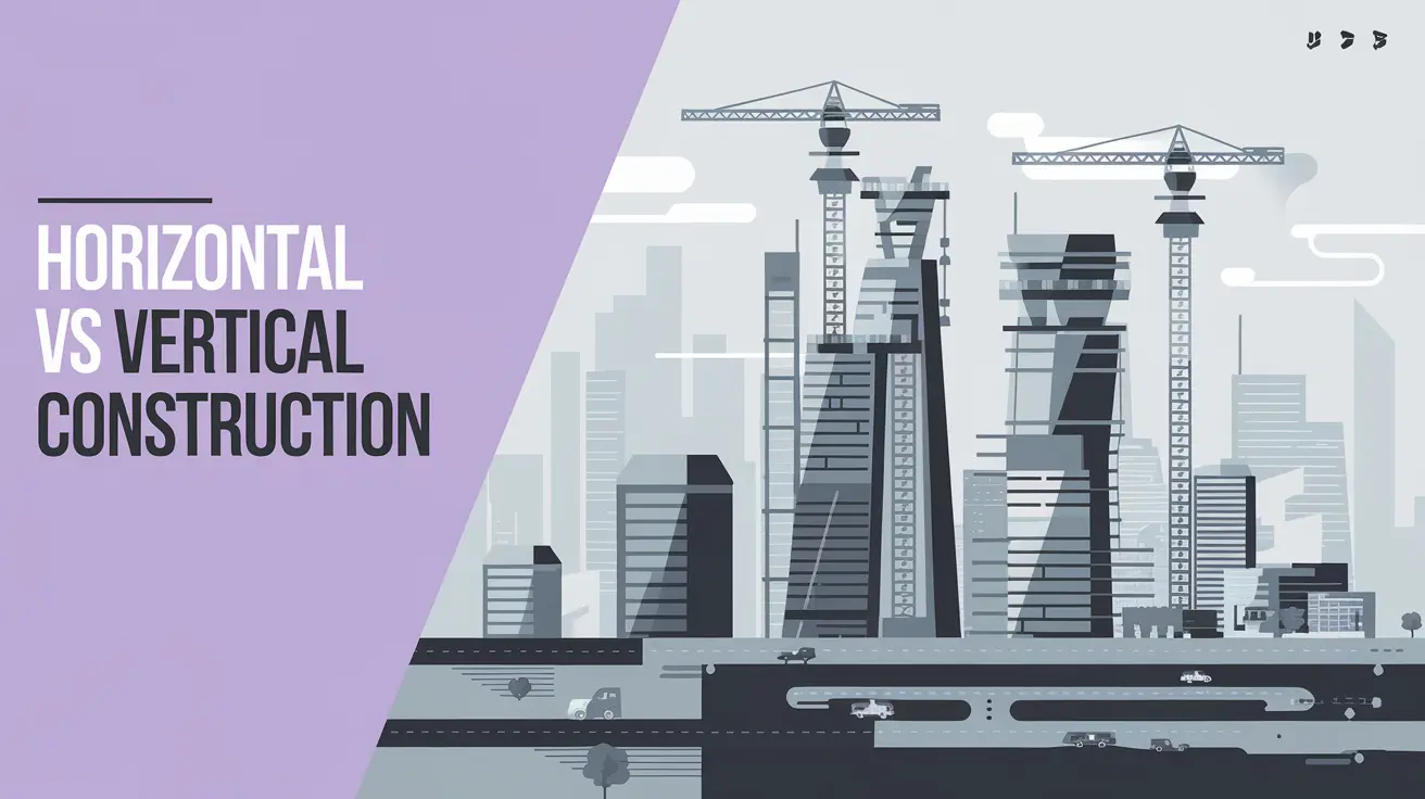
Illustration comparing horizontal vs vertical construction, showing highways below and skyscrapers under construction above.

Every construction project falls into one of two categories: horizontal vs vertical construction. If you’ve ever worked on an infrastructure project like roads, bridges, or railways, you’ve dealt with horizontal construction. On the other hand, if you’ve been involved in constructing high-rise buildings, apartments, or office towers, you’ve worked with vertical construction. But Which one is right for your project? In this guide, we’ll break down the key differences, similarities, and use cases of both construction types. We’ll also explore how BIM (Building Information Modeling) is transforming both horizontal and vertical construction projects. So, if you’re an AEC professional looking to make an informed decision, let’s dive in! What Is Horizontal Construction? Horizontal construction refers to infrastructure projects that expand outward across large areas rather than growing vertically. These projects are typically associated with transportation, land development, and large-scale civil engineering works. They serve as the backbone of a nation’s economy by enabling connectivity and supporting industries like logistics, trade, and public services.  Key Characteristics of Horizontal Construction Large-Scale Land Development Horizontal construction requires extensive land preparation, including site grading, leveling, and environmental impact assessments. Engineers must ensure the land is stable and suitable for infrastructure projects like roads, railways, and airports. Focus on Transportation and Infrastructure Most horizontal construction projects involve transportation networks such as highways, bridges, and railway systems. These developments enhance connectivity, facilitate trade, and improve mobility for urban and rural areas. Heavy-Duty Machinery and Equipment The construction process relies on specialized machinery such as excavators, bulldozers, and asphalt pavers. These machines enable large-scale earthmoving, material transportation, and structural reinforcement for durable infrastructure. Complex Engineering and Surveying Detailed surveys and engineering analyses are essential before project execution. Factors like soil stability, topography, and drainage must be evaluated to prevent structural failures and environmental risks. Long Project Timelines and High Budgets Horizontal construction projects often take years to complete due to their large scale and complex logistics. Government funding and public-private partnerships play a crucial role in financing these high-cost developments. Examples of Horizontal Construction 1. Highways and Roads Highways and roads are fundamental infrastructure projects designed to support transportation networks. These projects involve extensive land development, grading, and asphalt paving to create durable routes for vehicles. 2. Bridges and Overpasses Bridges connect different regions by spanning over water bodies, valleys, or roads. They require advanced engineering techniques to ensure structural integrity and resistance to environmental factors like wind and water currents. 3. Railways and Metro Systems Rail networks, including high-speed trains and metro systems, are crucial for urban and intercity transportation. Their construction involves track laying, tunnel excavation, and integration with transit hubs. 4. Airport Runways and Terminals Airports consist of vast horizontal structures such as runways, taxiways, and terminals. These projects require precise grading and paving to support aircraft operations and passenger movement. 5. Dams and Water Management Systems Dams control water flow for hydroelectric power generation, irrigation, and flood management. Their construction involves large-scale excavation, concrete placement, and reinforcement to withstand immense water pressure. What is Vertical Construction? Vertical construction refers to the process of building structures that expand upwards rather than outwards. This type of construction is commonly seen in urban environments where land availability is limited, making it essential to build taller rather than wider. Vertical construction projects include high-rise buildings, residential apartments, commercial complexes, hospitals, and skyscrapers. These structures rely on strong foundations, advanced engineering, and efficient space utilization to maximize their functionality. Key Characteristics of Vertical Construction 1. Height and Multi-Level Structures Vertical construction is defined by its multiple floors and towering designs. Unlike horizontal buildings, which spread across large areas, vertical structures are built upwards, making them ideal for space-constrained locations. 2. Complex Structural Engineering Since these buildings must support significant weight over multiple stories, they require reinforced concrete, steel frameworks, and deep foundations to ensure structural integrity. Wind resistance and earthquake-proofing are also critical considerations. 3. Advanced Construction Methods Vertical construction incorporates modern techniques such as prefabrication, modular construction, and high-strength materials to enhance efficiency and safety. Cranes, scaffolding, and elevators are essential for working at great heights. 4. Urban and Space-Efficient Design Most vertical buildings are found in cities where space is a premium. Skyscrapers, high-rise apartments, and commercial towers allow for high population density without occupying excessive land. 5. Integration of Mechanical and Safety Systems Due to their height, these buildings require specialized HVAC, plumbing, fire suppression, and elevator systems to ensure comfort, safety, and accessibility for occupants. Examples of Vertical Construction 1. High-Rise Buildings High-rise buildings, including skyscrapers and office towers, define modern city skylines. These structures require strong foundations, steel frameworks, and advanced materials to support their height while withstanding wind and seismic forces. 2. Residential Apartments and Condominiums Multi-story residential buildings house numerous families and individuals within a compact footprint. They require efficient space planning, structural reinforcements, and high-quality finishes to ensure durability and comfort for occupants. 3. Commercial and Office Buildings Corporate offices, shopping malls, and business complexes fall under this category. These buildings are designed with large open spaces, modern aesthetics, and advanced HVAC systems to create functional work and retail environments. 4. Hotels and Hospitality Buildings Hotels often include multiple floors with guest rooms, conference halls, and recreational areas. Their construction involves detailed architectural planning, premium interior design, and high-quality materials to ensure a luxurious guest experience. 5. Hospitals and Healthcare Facilities Hospitals require specialized construction techniques to support medical equipment, emergency services, and patient care facilities. They incorporate reinforced structures, advanced ventilation systems, and high-grade electrical and plumbing networks. Comparison: Horizontal vs Vertical Construction Similarities Between Horizontal and Vertical Construction While horizontal and vertical construction differ in their approach, they share several fundamental similarities that make them essential in the AEC (Architecture, Engineering, and Construction) industry. 1. Use of Advanced Construction Methods Both types of construction projects rely on modern construction technologies, such as Building Information Modeling (BIM), prefabrication, and automation, to enhance efficiency, accuracy, and project coordination. 2. Project Management Principles Horizontal and vertical construction projects require structured … Read more

BIM File Formats: Everything You Need to Know in 2025

An infographic featuring different BIM file formats and their connection with Bim software

Building Information Modeling (BIM) has become the backbone of modern architecture, engineering, and construction (AEC) projects. It allows professionals to design, simulate, and manage buildings more efficiently. But what makes seamless collaboration possible in BIM? The answer lies in BIM file formats. These BIM file formats determine how data is stored, shared, and transferred between different software. Some file formats are proprietary, meaning they are software-specific (like Revit files, .RVT), while others are non-proprietary, enabling cross-platform interoperability (like IFC files, .IFC). There are also specialized data formats like COBie, which focuses on structured facility management information. Choosing the right BIM file format is crucial because it impacts Collaboration: ensuring smooth data exchange between different professionals. Data Integrity: Preventing errors or loss during conversions. Project Efficiency: Speeding up approvals and workflows. Let’s explore what BIM file formats are, their types, and why they matter in modern construction! What are BIM file formats? BIM file formats refer to digital file types used in Building Information Modeling (BIM) to store and exchange 3D models, data, and project-related information. These formats are essential for collaboration, as they enable architects, engineers, and contractors to share building information across different BIM software platforms. Unlike traditional CAD files, which contain only geometric data, BIM files include intelligent, structured information such as: 3D geometry: the visual representation of the building. Material properties: specifications like concrete strength, insulation type, and more. Building components: doors, windows, HVAC systems, electrical systems, and plumbing. Project metadata: cost estimation, scheduling, and lifecycle information. Collaboration data: information about who made changes, when, and why. These files are the foundation of modern BIM software, allowing professionals to design, visualize, and analyze projects more effectively. They also enable clash detection, ensuring that structural, MEP (mechanical, electrical, plumbing), and architectural elements do not interfere with each other. Types of BIM File Formats BIM files can be classified into three main categories: 1️⃣ Proprietary BIM File Formats: Software-specific formats optimized for particular platforms. 2️⃣ Non-Proprietary BIM File Formats: Open-source formats that allow interoperability. 3️⃣ COBie (Construction Operations Building Information Exchange): A non-graphical format used for data exchange in facility management. Let’s explore each type in detail! 1. Proprietary BIM File Formats A proprietary file format is a BIM file format developed and controlled by a specific software vendor. These formats are designed for high performance and advanced features within their native software but often require conversion to be used in other programs. Common Proprietary BIM File Formats 🔹 Revit Files (.RVT, .RFA, .RTE) Used in Autodesk Revit, a leading BIM software. RVT stores 3D models, parametric data, and metadata. RFA: Contains Revit families (predefined components like windows, doors, and furniture). .RTE: Serves as a template file to standardize project settings. 🔹 Navisworks Files (.NWD, .NWF, .NWC) Used in Autodesk Navisworks for clash detection and project coordination. NWD: A read-only format for sharing finalized models. NWF: References multiple files for federated model coordination. NWC: A lightweight version of the BIM model optimized for quick navigation. 🔹 Archicad Files (.PLN, .PLA, .MOD, .GSM) Exclusive to Graphisoft Archicad, a BIM software for architectural design. PLAN: Contains full project data. PLA: Includes additional external references for collaboration. GSM stores library parts such as furniture and fixtures. 🔹 Tekla Structures Files (.TBP, .TSM, .IFC) Used in Tekla Structures for structural engineering and steel detailing. Supports advanced reinforcement modeling and construction planning. While proprietary formats provide powerful features, they can create compatibility challenges when working with professionals using different BIM tools. 2. Non-Proprietary BIM File Formats (Open Formats) Non-proprietary file formats, also known as open formats, are vendor-neutral file types designed for interoperability between different BIM software. These formats ensure smooth collaboration and data exchange without software restrictions. Common Non-Proprietary BIM File Formats 🔹 IFC File Format (.IFC) Industry Foundation Classes (IFC) is the most widely used open BIM format. Developed by buildingSMART International to promote cross-platform compatibility. Contains 3D geometry, materials, project phases, and metadata. Compatible with Revit, Archicad, Tekla, Bentley, and other major BIM software. 🔹 DXF (Drawing Exchange Format) Developed by Autodesk for 2D and 3D CAD file sharing. Compatible with both BIM and CAD software. 🔹 DWG (AutoCAD Drawing File) A standard 2D/3D drafting format used in AutoCAD, Revit, and Navisworks. 🔹 gbXML (Green Building XML) Designed for energy analysis and sustainability modeling. Helps BIM software interact with building performance tools. These open formats allow data preservation and exchange, making them essential for long-term project management. 3. COBie COBie (Construction Operations Building Information Exchange) is a data format for storing facility management information rather than 3D modeling data. 🔹 Uses Excel, XML, or IFC formats. 🔹 Stores equipment details, warranties, and maintenance schedules. 🔹 Ensures structured handover of building data after construction. COBie is widely used in government projects and large-scale infrastructure developments. Why Do BIM File Formats Matter? Seamless Collaboration: Different teams use different BIM software. Compatible file formats like IFC ensure smooth data exchange, preventing misinterpretation and workflow issues. Data Accuracy: BIM files store crucial project data. Converting between formats can lead to data loss, making open formats like IFC and COBIE essential. Software Interoperability: Projects involve various BIM tools. Standardized formats ensure seamless integration across software platforms like Revit, Navisworks, and Tekla. Long-Term Usability: Proprietary formats may become obsolete. Open formats like IFC ensure data remains accessible for facility management and future renovations. Cost and Efficiency: Incompatible formats cause delays and rework. Using the right format saves time, reduces errors, and ensures efficient project execution. Conclusion BIM file formats play a crucial role in modern construction by enabling seamless collaboration, data accuracy, and interoperability across different software platforms. Choosing the right file format—whether proprietary or non-proprietary—directly impacts project efficiency, cost, and long-term usability. Open formats like IFC and COBie promote accessibility and future-proofing, ensuring that BIM data remains usable even as technology evolves. As the construction industry embraces digital transformation, understanding BIM file formats is no longer optional—it’s essential. By leveraging the right formats, professionals can streamline workflows, reduce errors, and enhance project outcomes. Whether you’re working on a small project or a … Read more

What’s LOD in BIM? A Simple Guide for 2025

An infographic displaying the level of development LOD in BIM.

The construction industry is evolving rapidly, with Building Information Modeling (BIM) revolutionizing how projects are designed, managed, and executed. However, to fully leverage BIM, professionals must understand a crucial aspect—The level of Development LOD in BIM. So, what exactly is LOD in BIM? In simple terms, it refers to the accuracy, detail, and reliability of a BIM model at different project stages. It ensures that architects, engineers, and contractors work with precise, standardized information, reducing conflicts and enhancing efficiency. Think of it like this—at the beginning of a project, your model is like a rough sketch (LOD 100). As the design progresses, it becomes more detailed and specific, eventually turning into a highly accurate, construction-ready model (LOD 400). Once built, the model reflects the actual structure (LOD 500). Understanding LOD in BIM is essential for AEC professionals, as it provides a structured workflow and helps teams collaborate seamlessly. In this guide, we’ll explore the origins of LOD, its different levels, benefits, software compatibility, and more. Let’s get started! The Origin of LOD in BIM Before BIM became an industry standard, architectural and engineering drawings were primarily created using 2D drafting techniques. This often led to miscommunication, design inconsistencies, and construction errors, resulting in costly rework. The need for a structured framework to define the progression of a BIM model led to the development of Level of Development (LOD) standards. The American Institute of Architects (AIA) introduced the concept of LOD in BIM in 2008, providing a systematic approach to define how much information and detail should be included at different project stages. This framework was further refined by the BIMForum, ensuring a common language for all project stakeholders. Today, LOD has become a global standard adopted in architecture, engineering, and construction (AEC) industries worldwide. BIM Levels of Development (LOD) as Defined by AIA The American Institute of Architects (AIA) introduced Level of Development (LOD) standards to establish a structured approach to BIM model accuracy and reliability at different project stages. Each LOD stage represents a progression in detail and accuracy, from initial conceptual sketches (LOD 100) to fully detailed, as-built models (LOD 500). Let’s break down each level and explore its significance in real-world construction and project management. 1. LOD 100 – Conceptual Design At this stage, the BIM model is in its infancy—it’s essentially a 3D representation of the project’s conceptual idea. However, it lacks specific details, precise dimensions, materials, or technical data. Characteristics of LOD 100: ✔️ The model is primarily used for mass studies and initial planning. ✔️ It represents basic shapes, volumes, and spatial relationships but lacks exact geometry. ✔️ No detailed specifications, dimensions, or construction-ready elements are included. ✔️ Placeholder objects are used instead of real-world elements. Example: Imagine you’re designing a new office building. At LOD 100, the model only includes the general shape and footprint of the structure—think of it as a rough sketch or 3D block model. While it provides a basic idea of the project’s scope and size, it doesn’t contain details like wall thickness, material types, or structural integrity. Use Cases: 📌 Early-stage feasibility studies to determine if the project is viable. 📌 Mass modeling for preliminary space planning and zoning analysis. 📌 Client presentations to showcase the general concept before committing to specifics. 2. LOD 200 – Schematic Design At LOD 200, the model becomes more defined, but it still lacks final accuracy and constructability. It introduces approximate dimensions, materials, and relationships between building components, yet elements remain generic and non-specific. Characteristics of LOD 200: ✔️ Geometry is more refined than LOD 100, but still not final. ✔️ Includes preliminary material selections, but not manufacturer-specific details. ✔️ Dimensions and locations of elements are approximate, not exact. ✔️ Some early cost estimates can be made based on general assumptions. Example: A LOD 200 door in your BIM model will have a defined shape, rough dimensions, and an estimated material type (wood, metal, or glass), but it won’t yet specify the exact manufacturer, fire rating, or hinge placement. Use Cases: 📌 Early coordination between architects, engineers, and contractors. 📌 Rough cost estimates for budgeting purposes. 📌 Design iterations and approvals before moving into detailed design. 3. LOD 300 – Detailed Design At this stage, the BIM model becomes much more refined and accurate. The geometry, dimensions, materials, and installation details are precisely defined—making it reliable for construction documentation. Characteristics of LOD 300: ✔️ Accurate dimensions, locations, and shapes of all components. ✔️ Includes real-world material properties (e.g., concrete strength, steel grade). ✔️ Elements are ready for clash detection and early-stage coordination. ✔️ The model can be used for construction drawings, section cuts, and shop drawings. Example: A LOD 300 structural beam includes precise length, width, depth, material type (steel, concrete, wood), and weight capacity. Contractors can now use this information directly in construction planning. Use Cases: 📌 Detailed design coordination between MEP, structural, and architectural teams. 📌 Construction drawings & documentation generation. 📌 Clash detection and resolving issues before construction begins. 4. LOD 350 – Construction Documentation At LOD 350, the BIM model gains a higher level of detail, integrating how elements interact with each other. Unlike LOD 300, which focuses on individual components, LOD 350 adds connections and interfaces between them. Characteristics of LOD 350: ✔️ Accurate detailing of how components are installed, joined, and connected. ✔️ Includes supports, fasteners, brackets, and attachment points. ✔️ Geometry now reflects real-world constructability. ✔️ Elements interact with adjacent building systems (e.g., HVAC ducts passing through walls). Example: A LOD 350 steel beam will not only show its dimensions and material properties but will also include bolted or welded connections, base plates, anchor bolts, and attachment brackets. Use Cases: 📌 Construction sequencing and site coordination. 📌 Structural and MEP integration—ensuring everything fits together seamlessly. 📌 More accurate cost estimation as constructability details are finalized. 5. LOD 400 – Fabrication & Assembly At LOD 400, the model becomes manufacturing-ready, containing highly accurate fabrication details. Every component is precisely modeled for direct prefabrication and assembly. … Read more

How BIM Clash Detection Can Save Your Time and Money

3D visualization of BIM clash detection with infrastructure highlights and benefits listed

The construction industry faces constant challenges—tight deadlines, budget constraints, and the ever-present risk of design errors. Managing design conflicts between architectural, structural, and MEP systems is one of the biggest hurdles in any project. Even a small design clash can lead to delays, costly rework, and material wastage, significantly impacting the project’s bottom line. This is where BIM clash detection plays a transformative role, helping project teams identify and resolve design conflicts before construction begins, ensuring better coordination and efficiency. By utilizing Building Information Modeling (BIM), teams can eliminate errors, enhance coordination, and streamline project execution. With the integration of advanced navisworks clash detection tools, modern construction firms can identify, analyze, and resolve design clashes in a virtual environment, ensuring smooth project workflows and better decision-making. So, how exactly does BIM clash detection work? Why is it so essential for construction projects? And what software tools can help implement it effectively? Let’s explore everything you need to know. What is BIM Clash Detection? At its core, BIM clash detection is a process that identifies design conflicts between different building systems within a digital model before the physical construction begins. These conflicts, known as clashes, occur when two or more components intersect or interfere with each other in ways that would cause problems during construction. Traditionally, detecting clashes required manual review of 2D drawings, which was time-consuming and error-prone. With BIM software, all design elements—including architectural, structural, and MEP components are integrated into a coordinated 3D model, where clash detection algorithms can quickly scan for inconsistencies. Once clashes are identified, teams can resolve them digitally rather than dealing with expensive modifications during construction. This reduces the risk of rework, delays, and material wastage, making BIM clash detection a crucial process for achieving cost-effective, efficient, and high-quality construction projects. Why BIM Clash Detection is Needed? Modern buildings are highly complex structures involving multiple disciplines—architectural, structural, mechanical, electrical, and plumbing systems—all working in harmony. Without proper coordination and clash detection, the risk of design conflicts, rework, and budget overruns increases significantly. One of the primary reasons BIM clash detection is necessary is the integration of MEP coordination into structural and architectural designs. MEP coordination is crucial because these systems must fit within tight spatial constraints without interfering with beams, columns, or other structural components. Consider a scenario where a large HVAC duct is designed to pass through a space already occupied by a load-bearing column. If this clash is not detected in the early stages, it could lead to costly on-site modifications, project delays, and potential safety risks. By implementing BIM clash detection, teams can: Identify and resolve design errors early, reducing the need for on-site fixes. Improve communication between architects, engineers, and contractors, ensuring a coordinated workflow. Minimize project risks by proactively addressing potential conflicts. Optimize scheduling by preventing workflow disruptions caused by unexpected design changes. Ultimately, It leads to better decision-making, improved resource allocation, and a more efficient construction process. Benefits of BIM Clash Detection 1. Minimize Costly Rework Clashes detected during construction require expensive modifications, material replacements, and additional labor. Resolving clashes in the design phase eliminates these costs, ensuring that construction progresses smoothly without costly interruptions 2. Enhance MEP Coordination MEP coordination is critical in modern construction. Without proper use of this technology, mechanical systems may conflict with structural elements, leading to expensive modifications and workflow disruptions. Early detection ensures that all MEP systems are properly placed and integrated into the design. 3. Reduce Project Delays A construction delay can result in financial losses, legal disputes, and resource mismanagement. BIM clash detection helps prevent unexpected site conflicts, keeping projects on schedule and reducing overall risk. 4. Improve Safety Compliance Structural and soft clash issues can compromise safety regulations and building codes. By using it, teams can identify design conflicts that could lead to structural weaknesses or hazardous work conditions, ensuring compliance with industry safety standards. 5. Optimize Resource Utilization Material wastage is a major challenge in construction. Clashes often lead to unnecessary material ordering, transportation, and disposal costs. BIM clash detection ensures that all building elements are optimally designed and placed, reducing waste and improving resource efficiency. Types of Clashes in BIM 1. Hard Clashes A hard clash happens when two building components physically occupy the same space. For example, a structural column conflicting with an HVAC duct. These clashes are the most critical to resolve as they directly affect the buildability of the project. 2. Soft Clashes A soft clash occurs when components violate design tolerances or safety clearances. These are not direct physical conflicts but could lead to maintenance difficulties or operational inefficiencies. For instance, a mechanical system without enough clearance for servicing would be a soft clash. 3. Workflow Clashes These clashes arise due to scheduling conflicts or work sequence issues. For example, if an MEP team is scheduled to install wiring before the drywall is completed, it could create a workflow clash that disrupts the project timeline. Clash Detection Software To implement BIM clash detection effectively, construction firms rely on specialized clash detection software that integrates with BIM platforms. These tools help teams identify, analyze, and resolve design conflicts before construction begins, ensuring a smooth and error-free workflow. 1. Navisworks Navisworks clash detection is one of the most powerful tools used for model coordination, clash detection, and project visualization. Developed by Autodesk, it allows project teams to merge multiple 3D models from different disciplines into a single federated model to detect and resolve clashes before actual construction starts. Navisworks clash detection provides advanced clash detection algorithms that analyze thousands of building components simultaneously, identifying both hard and soft clashes. The software offers 4D simulation capabilities, enabling teams to visualize how construction sequences will unfold over time and predict workflow issues before they occur. Additionally, it integrates seamlessly with Revit, AutoCAD, and other BIM tools, making it a go-to solution for large-scale projects that require precise coordination and collaboration. 2. Autodesk BIM Collaborate Autodesk BIM Collaborate is a cloud-based clash detection and coordination platform designed … Read more

What is BIM in the AEC Industry?& its Importance in 2025

A featured image showing What is bim and its benefits in 2025

The construction and architecture industries are rapidly evolving, and Building Information Modeling (BIM) is a game changer. BIM is a product, yes, but it is also a method that enables architects, engineers, and construction (AEC) professionals to work collaboratively and create exceptional projects. Studies indicate that up to 70 percent of construction firms have adopted BIM to improve efficiency and save more. In this article, we’ll talk about what is BIM. what information sharing it facilitates, why different professions benefit from it, how we use BIM in the real world, and where BIM will go next in the AEC industry. What is BIM? Building Information Modeling (BIM) is a new digital process leading the way in how buildings and infrastructure are developed, built, and managed. It is a common data environment for architects, engineers, contractors, and other stakeholders to work together in one environment throughout a project’s lifecycle. Definition of BIM by different institutions: The National Institute of Building Sciences (NIBS) defines Building Information Modeling (BIM) as a digital representation of a facility’s physical and functional characteristics. A BIM is a shared knowledge resource for information about a facility forming a reliable basis for decisions during its life-cycle, defined as existing from earliest conception to demolition. The Royal Institute of British Architects (RIBA) describes Building Information Modelling (BIM) as the process of creating and managing information for a built asset throughout its lifecycle—from planning and design to construction and operation.  The American Institute of Architects (AIA) defines building information modeling (BIM) as a digital representation of or part of a project. BIM is a collaborative process that uses software and data to create and manage a building’s information throughout its lifecycle How Does BIM Share Information? As a central hub, BIM gathers all project-related data and provides a mechanism for communication and collaboration among all project stakeholders. Here’s a step-by-step breakdown of how BIM facilitates seamless information sharing: Data Input: In this process, architects, engineers, and other professionals create and enter detailed information into a shared 3D model that includes design, materials, and structural details. Centralized Model Access: The model is stored in cloud-based BIM software like Autodesk BIM 360 so that the model is readily available to all members of the team. This centralization eliminates data silos and allows everyone to work from the same, up-to-date information. Real-Time Updates: Changes made to the model are automatically reflected, so it’s possible to work in real time and minimize the possibility of miscommunication. Interoperability: BIM allows different file formats, such as IFC, DWG, and so on, allowing different tools and software to work in parallel. Visualization and Reporting: It allows for detailed reporting, clash detection, and design visualization in 3D for stakeholders to extract, and perform better decision-making for project management. What BIM Can Do: Benefits Across Professions It tailored advantages for various roles of BIM in the AEC industry that enable efficiency and innovation within the industry. Let’s delve deeper into the benefits of each profession: BIM for architects: Enhanced Visualization: Thanks to BIM, architects can create detailed 3D models that clearly and realistically map out their designs. The benefits of this are that clients can see what the finished product will look like, and it forms a strong basis for design decisions. Clash Detection: Architects who can identify and resolve design conflicts early will avoid costly rework, and the resulting project will proceed more smoothly. Creative Flexibility: Architects can experiment with innovative designs, materials, and layouts with BIM tools, and as a result, modern, aesthetically pleasing, and sustainable structures come to pass. BIM for Engineers: Integrated Designs: A structural engineer can work on mechanical, electrical, and plumbing (MEP) systems that can be seamlessly combined into a single cohesive BIM model, improving compatibility and reducing errors. Advanced Simulations: With BIM software, engineers can test for structural performance, digital representation, energy analysis, and load testing, so they can optimize their designs for safety and efficiency. Improved Documentation: Engineering details are precise and easily accessible for all stakeholders, and are documented with comprehensive documentation. BIM for Construction Firms: 4D Scheduling: BIM integrates time-based data with a 3D BIM model, which aids construction firms in planning and visualizing their project timelines. 5D Cost Estimation: Quantity take-offs and cost calculations are automated in BIM, and budgets are accurate and reduce financial risk. Improved Site Coordination: Real-time updates and detailed plans benefit on-site teams that can reduce delays and increase overall productivity. BIM for Facility Managers: Lifecycle Asset Management: BIM provides detailed as-built models that make the maintenance and operation of building systems easier. Real-Time Data Access: BIM integration with IoT systems provides real-time data to facility managers. It enables better building system monitoring to achieve better operational efficiency and occupant comfort. Enhanced Sustainability: BIM allows facility managers to study how energy is used and therefore to identify inefficiencies. It is supportive of the process for practicing sustainability, and it may enable green building certifications such as LEED. BIM in Practice: Successful Case Studies BIM’s real-world applications show how it is a force for change in projects of every kind. Here are two notable examples: Sydney Opera House Renovation: An entire opera house, the Sydney Opera House, an iconic symbol of Australia, was renovated to modernize its facilities while maintaining its singular design. Using Building Information Modeling (BIM), the project team made a digital twin of the building so that they would have an accurate 3D representation of the BIM execution plan for the restoration.  It enabled the team to simulate changes to the building’s historic structure without disturbing the building itself, including seating, acoustics, and lighting. Clash detection was facilitated by BIM and resolved early between mechanical, electrical, and structural systems. By providing real-time collaboration between architects, engineers, and heritage experts, the project was completed on time and within budget, while also acting to preserve and improve the Opera House’s architectural heritage for future performances. Shanghai Tower: China’s tallest building is Shanghai Tower, which comes in at 632 meters and is the second … Read more