BIM File Formats: Everything You Need to Know in 2025

An infographic featuring different BIM file formats and their connection with Bim software

Building Information Modeling (BIM) has become the backbone of modern architecture, engineering, and construction (AEC) projects. It allows professionals to design, simulate, and manage buildings more efficiently. But what makes seamless collaboration possible in BIM? The answer lies in BIM file formats. These BIM file formats determine how data is stored, shared, and transferred between different software. Some file formats are proprietary, meaning they are software-specific (like Revit files, .RVT), while others are non-proprietary, enabling cross-platform interoperability (like IFC files, .IFC). There are also specialized data formats like COBie, which focuses on structured facility management information. Choosing the right BIM file format is crucial because it impacts Collaboration: ensuring smooth data exchange between different professionals. Data Integrity: Preventing errors or loss during conversions. Project Efficiency: Speeding up approvals and workflows. Let’s explore what BIM file formats are, their types, and why they matter in modern construction! What are BIM file formats? BIM file formats refer to digital file types used in Building Information Modeling (BIM) to store and exchange 3D models, data, and project-related information. These formats are essential for collaboration, as they enable architects, engineers, and contractors to share building information across different BIM software platforms. Unlike traditional CAD files, which contain only geometric data, BIM files include intelligent, structured information such as: 3D geometry: the visual representation of the building. Material properties: specifications like concrete strength, insulation type, and more. Building components: doors, windows, HVAC systems, electrical systems, and plumbing. Project metadata: cost estimation, scheduling, and lifecycle information. Collaboration data: information about who made changes, when, and why. These files are the foundation of modern BIM software, allowing professionals to design, visualize, and analyze projects more effectively. They also enable clash detection, ensuring that structural, MEP (mechanical, electrical, plumbing), and architectural elements do not interfere with each other. Types of BIM File Formats BIM files can be classified into three main categories: 1️⃣ Proprietary BIM File Formats: Software-specific formats optimized for particular platforms. 2️⃣ Non-Proprietary BIM File Formats: Open-source formats that allow interoperability. 3️⃣ COBie (Construction Operations Building Information Exchange): A non-graphical format used for data exchange in facility management. Let’s explore each type in detail! 1. Proprietary BIM File Formats A proprietary file format is a BIM file format developed and controlled by a specific software vendor. These formats are designed for high performance and advanced features within their native software but often require conversion to be used in other programs. Common Proprietary BIM File Formats 🔹 Revit Files (.RVT, .RFA, .RTE) Used in Autodesk Revit, a leading BIM software. RVT stores 3D models, parametric data, and metadata. RFA: Contains Revit families (predefined components like windows, doors, and furniture). .RTE: Serves as a template file to standardize project settings. 🔹 Navisworks Files (.NWD, .NWF, .NWC) Used in Autodesk Navisworks for clash detection and project coordination. NWD: A read-only format for sharing finalized models. NWF: References multiple files for federated model coordination. NWC: A lightweight version of the BIM model optimized for quick navigation. 🔹 Archicad Files (.PLN, .PLA, .MOD, .GSM) Exclusive to Graphisoft Archicad, a BIM software for architectural design. PLAN: Contains full project data. PLA: Includes additional external references for collaboration. GSM stores library parts such as furniture and fixtures. 🔹 Tekla Structures Files (.TBP, .TSM, .IFC) Used in Tekla Structures for structural engineering and steel detailing. Supports advanced reinforcement modeling and construction planning. While proprietary formats provide powerful features, they can create compatibility challenges when working with professionals using different BIM tools. 2. Non-Proprietary BIM File Formats (Open Formats) Non-proprietary file formats, also known as open formats, are vendor-neutral file types designed for interoperability between different BIM software. These formats ensure smooth collaboration and data exchange without software restrictions. Common Non-Proprietary BIM File Formats 🔹 IFC File Format (.IFC) Industry Foundation Classes (IFC) is the most widely used open BIM format. Developed by buildingSMART International to promote cross-platform compatibility. Contains 3D geometry, materials, project phases, and metadata. Compatible with Revit, Archicad, Tekla, Bentley, and other major BIM software. 🔹 DXF (Drawing Exchange Format) Developed by Autodesk for 2D and 3D CAD file sharing. Compatible with both BIM and CAD software. 🔹 DWG (AutoCAD Drawing File) A standard 2D/3D drafting format used in AutoCAD, Revit, and Navisworks. 🔹 gbXML (Green Building XML) Designed for energy analysis and sustainability modeling. Helps BIM software interact with building performance tools. These open formats allow data preservation and exchange, making them essential for long-term project management. 3. COBie COBie (Construction Operations Building Information Exchange) is a data format for storing facility management information rather than 3D modeling data. 🔹 Uses Excel, XML, or IFC formats. 🔹 Stores equipment details, warranties, and maintenance schedules. 🔹 Ensures structured handover of building data after construction. COBie is widely used in government projects and large-scale infrastructure developments. Why Do BIM File Formats Matter? Seamless Collaboration: Different teams use different BIM software. Compatible file formats like IFC ensure smooth data exchange, preventing misinterpretation and workflow issues. Data Accuracy: BIM files store crucial project data. Converting between formats can lead to data loss, making open formats like IFC and COBIE essential. Software Interoperability: Projects involve various BIM tools. Standardized formats ensure seamless integration across software platforms like Revit, Navisworks, and Tekla. Long-Term Usability: Proprietary formats may become obsolete. Open formats like IFC ensure data remains accessible for facility management and future renovations. Cost and Efficiency: Incompatible formats cause delays and rework. Using the right format saves time, reduces errors, and ensures efficient project execution. Conclusion BIM file formats play a crucial role in modern construction by enabling seamless collaboration, data accuracy, and interoperability across different software platforms. Choosing the right file format—whether proprietary or non-proprietary—directly impacts project efficiency, cost, and long-term usability. Open formats like IFC and COBie promote accessibility and future-proofing, ensuring that BIM data remains usable even as technology evolves. As the construction industry embraces digital transformation, understanding BIM file formats is no longer optional—it’s essential. By leveraging the right formats, professionals can streamline workflows, reduce errors, and enhance project outcomes. Whether you’re working on a small project or a … Read more

What’s LOD in BIM? A Simple Guide for 2025

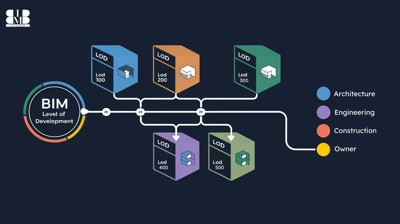
An infographic displaying the level of development LOD in BIM.

The construction industry is evolving rapidly, with Building Information Modeling (BIM) revolutionizing how projects are designed, managed, and executed. However, to fully leverage BIM, professionals must understand a crucial aspect—The level of Development LOD in BIM. So, what exactly is LOD in BIM? In simple terms, it refers to the accuracy, detail, and reliability of a BIM model at different project stages. It ensures that architects, engineers, and contractors work with precise, standardized information, reducing conflicts and enhancing efficiency. Think of it like this—at the beginning of a project, your model is like a rough sketch (LOD 100). As the design progresses, it becomes more detailed and specific, eventually turning into a highly accurate, construction-ready model (LOD 400). Once built, the model reflects the actual structure (LOD 500). Understanding LOD in BIM is essential for AEC professionals, as it provides a structured workflow and helps teams collaborate seamlessly. In this guide, we’ll explore the origins of LOD, its different levels, benefits, software compatibility, and more. Let’s get started! The Origin of LOD in BIM Before BIM became an industry standard, architectural and engineering drawings were primarily created using 2D drafting techniques. This often led to miscommunication, design inconsistencies, and construction errors, resulting in costly rework. The need for a structured framework to define the progression of a BIM model led to the development of Level of Development (LOD) standards. The American Institute of Architects (AIA) introduced the concept of LOD in BIM in 2008, providing a systematic approach to define how much information and detail should be included at different project stages. This framework was further refined by the BIMForum, ensuring a common language for all project stakeholders. Today, LOD has become a global standard adopted in architecture, engineering, and construction (AEC) industries worldwide. BIM Levels of Development (LOD) as Defined by AIA The American Institute of Architects (AIA) introduced Level of Development (LOD) standards to establish a structured approach to BIM model accuracy and reliability at different project stages. Each LOD stage represents a progression in detail and accuracy, from initial conceptual sketches (LOD 100) to fully detailed, as-built models (LOD 500). Let’s break down each level and explore its significance in real-world construction and project management. 1. LOD 100 – Conceptual Design At this stage, the BIM model is in its infancy—it’s essentially a 3D representation of the project’s conceptual idea. However, it lacks specific details, precise dimensions, materials, or technical data. Characteristics of LOD 100: ✔️ The model is primarily used for mass studies and initial planning. ✔️ It represents basic shapes, volumes, and spatial relationships but lacks exact geometry. ✔️ No detailed specifications, dimensions, or construction-ready elements are included. ✔️ Placeholder objects are used instead of real-world elements. Example: Imagine you’re designing a new office building. At LOD 100, the model only includes the general shape and footprint of the structure—think of it as a rough sketch or 3D block model. While it provides a basic idea of the project’s scope and size, it doesn’t contain details like wall thickness, material types, or structural integrity. Use Cases: 📌 Early-stage feasibility studies to determine if the project is viable. 📌 Mass modeling for preliminary space planning and zoning analysis. 📌 Client presentations to showcase the general concept before committing to specifics. 2. LOD 200 – Schematic Design At LOD 200, the model becomes more defined, but it still lacks final accuracy and constructability. It introduces approximate dimensions, materials, and relationships between building components, yet elements remain generic and non-specific. Characteristics of LOD 200: ✔️ Geometry is more refined than LOD 100, but still not final. ✔️ Includes preliminary material selections, but not manufacturer-specific details. ✔️ Dimensions and locations of elements are approximate, not exact. ✔️ Some early cost estimates can be made based on general assumptions. Example: A LOD 200 door in your BIM model will have a defined shape, rough dimensions, and an estimated material type (wood, metal, or glass), but it won’t yet specify the exact manufacturer, fire rating, or hinge placement. Use Cases: 📌 Early coordination between architects, engineers, and contractors. 📌 Rough cost estimates for budgeting purposes. 📌 Design iterations and approvals before moving into detailed design. 3. LOD 300 – Detailed Design At this stage, the BIM model becomes much more refined and accurate. The geometry, dimensions, materials, and installation details are precisely defined—making it reliable for construction documentation. Characteristics of LOD 300: ✔️ Accurate dimensions, locations, and shapes of all components. ✔️ Includes real-world material properties (e.g., concrete strength, steel grade). ✔️ Elements are ready for clash detection and early-stage coordination. ✔️ The model can be used for construction drawings, section cuts, and shop drawings. Example: A LOD 300 structural beam includes precise length, width, depth, material type (steel, concrete, wood), and weight capacity. Contractors can now use this information directly in construction planning. Use Cases: 📌 Detailed design coordination between MEP, structural, and architectural teams. 📌 Construction drawings & documentation generation. 📌 Clash detection and resolving issues before construction begins. 4. LOD 350 – Construction Documentation At LOD 350, the BIM model gains a higher level of detail, integrating how elements interact with each other. Unlike LOD 300, which focuses on individual components, LOD 350 adds connections and interfaces between them. Characteristics of LOD 350: ✔️ Accurate detailing of how components are installed, joined, and connected. ✔️ Includes supports, fasteners, brackets, and attachment points. ✔️ Geometry now reflects real-world constructability. ✔️ Elements interact with adjacent building systems (e.g., HVAC ducts passing through walls). Example: A LOD 350 steel beam will not only show its dimensions and material properties but will also include bolted or welded connections, base plates, anchor bolts, and attachment brackets. Use Cases: 📌 Construction sequencing and site coordination. 📌 Structural and MEP integration—ensuring everything fits together seamlessly. 📌 More accurate cost estimation as constructability details are finalized. 5. LOD 400 – Fabrication & Assembly At LOD 400, the model becomes manufacturing-ready, containing highly accurate fabrication details. Every component is precisely modeled for direct prefabrication and assembly. … Read more

How BIM Clash Detection Can Save Your Time and Money

3D visualization of BIM clash detection with infrastructure highlights and benefits listed

The construction industry faces constant challenges—tight deadlines, budget constraints, and the ever-present risk of design errors. Managing design conflicts between architectural, structural, and MEP systems is one of the biggest hurdles in any project. Even a small design clash can lead to delays, costly rework, and material wastage, significantly impacting the project’s bottom line. This is where BIM clash detection plays a transformative role, helping project teams identify and resolve design conflicts before construction begins, ensuring better coordination and efficiency. By utilizing Building Information Modeling (BIM), teams can eliminate errors, enhance coordination, and streamline project execution. With the integration of advanced navisworks clash detection tools, modern construction firms can identify, analyze, and resolve design clashes in a virtual environment, ensuring smooth project workflows and better decision-making. So, how exactly does BIM clash detection work? Why is it so essential for construction projects? And what software tools can help implement it effectively? Let’s explore everything you need to know. What is BIM Clash Detection? At its core, BIM clash detection is a process that identifies design conflicts between different building systems within a digital model before the physical construction begins. These conflicts, known as clashes, occur when two or more components intersect or interfere with each other in ways that would cause problems during construction. Traditionally, detecting clashes required manual review of 2D drawings, which was time-consuming and error-prone. With BIM software, all design elements—including architectural, structural, and MEP components are integrated into a coordinated 3D model, where clash detection algorithms can quickly scan for inconsistencies. Once clashes are identified, teams can resolve them digitally rather than dealing with expensive modifications during construction. This reduces the risk of rework, delays, and material wastage, making BIM clash detection a crucial process for achieving cost-effective, efficient, and high-quality construction projects. Why BIM Clash Detection is Needed? Modern buildings are highly complex structures involving multiple disciplines—architectural, structural, mechanical, electrical, and plumbing systems—all working in harmony. Without proper coordination and clash detection, the risk of design conflicts, rework, and budget overruns increases significantly. One of the primary reasons BIM clash detection is necessary is the integration of MEP coordination into structural and architectural designs. MEP coordination is crucial because these systems must fit within tight spatial constraints without interfering with beams, columns, or other structural components. Consider a scenario where a large HVAC duct is designed to pass through a space already occupied by a load-bearing column. If this clash is not detected in the early stages, it could lead to costly on-site modifications, project delays, and potential safety risks. By implementing BIM clash detection, teams can: Identify and resolve design errors early, reducing the need for on-site fixes. Improve communication between architects, engineers, and contractors, ensuring a coordinated workflow. Minimize project risks by proactively addressing potential conflicts. Optimize scheduling by preventing workflow disruptions caused by unexpected design changes. Ultimately, It leads to better decision-making, improved resource allocation, and a more efficient construction process. Benefits of BIM Clash Detection 1. Minimize Costly Rework Clashes detected during construction require expensive modifications, material replacements, and additional labor. Resolving clashes in the design phase eliminates these costs, ensuring that construction progresses smoothly without costly interruptions 2. Enhance MEP Coordination MEP coordination is critical in modern construction. Without proper use of this technology, mechanical systems may conflict with structural elements, leading to expensive modifications and workflow disruptions. Early detection ensures that all MEP systems are properly placed and integrated into the design. 3. Reduce Project Delays A construction delay can result in financial losses, legal disputes, and resource mismanagement. BIM clash detection helps prevent unexpected site conflicts, keeping projects on schedule and reducing overall risk. 4. Improve Safety Compliance Structural and soft clash issues can compromise safety regulations and building codes. By using it, teams can identify design conflicts that could lead to structural weaknesses or hazardous work conditions, ensuring compliance with industry safety standards. 5. Optimize Resource Utilization Material wastage is a major challenge in construction. Clashes often lead to unnecessary material ordering, transportation, and disposal costs. BIM clash detection ensures that all building elements are optimally designed and placed, reducing waste and improving resource efficiency. Types of Clashes in BIM 1. Hard Clashes A hard clash happens when two building components physically occupy the same space. For example, a structural column conflicting with an HVAC duct. These clashes are the most critical to resolve as they directly affect the buildability of the project. 2. Soft Clashes A soft clash occurs when components violate design tolerances or safety clearances. These are not direct physical conflicts but could lead to maintenance difficulties or operational inefficiencies. For instance, a mechanical system without enough clearance for servicing would be a soft clash. 3. Workflow Clashes These clashes arise due to scheduling conflicts or work sequence issues. For example, if an MEP team is scheduled to install wiring before the drywall is completed, it could create a workflow clash that disrupts the project timeline. Clash Detection Software To implement BIM clash detection effectively, construction firms rely on specialized clash detection software that integrates with BIM platforms. These tools help teams identify, analyze, and resolve design conflicts before construction begins, ensuring a smooth and error-free workflow. 1. Navisworks Navisworks clash detection is one of the most powerful tools used for model coordination, clash detection, and project visualization. Developed by Autodesk, it allows project teams to merge multiple 3D models from different disciplines into a single federated model to detect and resolve clashes before actual construction starts. Navisworks clash detection provides advanced clash detection algorithms that analyze thousands of building components simultaneously, identifying both hard and soft clashes. The software offers 4D simulation capabilities, enabling teams to visualize how construction sequences will unfold over time and predict workflow issues before they occur. Additionally, it integrates seamlessly with Revit, AutoCAD, and other BIM tools, making it a go-to solution for large-scale projects that require precise coordination and collaboration. 2. Autodesk BIM Collaborate Autodesk BIM Collaborate is a cloud-based clash detection and coordination platform designed … Read more

What is BIM in the AEC Industry?& its Importance in 2025

A featured image showing What is bim and its benefits in 2025

The construction and architecture industries are rapidly evolving, and Building Information Modeling (BIM) is a game changer. BIM is a product, yes, but it is also a method that enables architects, engineers, and construction (AEC) professionals to work collaboratively and create exceptional projects. Studies indicate that up to 70 percent of construction firms have adopted BIM to improve efficiency and save more. In this article, we’ll talk about what is BIM. what information sharing it facilitates, why different professions benefit from it, how we use BIM in the real world, and where BIM will go next in the AEC industry. What is BIM? Building Information Modeling (BIM) is a new digital process leading the way in how buildings and infrastructure are developed, built, and managed. It is a common data environment for architects, engineers, contractors, and other stakeholders to work together in one environment throughout a project’s lifecycle. Definition of BIM by different institutions: The National Institute of Building Sciences (NIBS) defines Building Information Modeling (BIM) as a digital representation of a facility’s physical and functional characteristics. A BIM is a shared knowledge resource for information about a facility forming a reliable basis for decisions during its life-cycle, defined as existing from earliest conception to demolition. The Royal Institute of British Architects (RIBA) describes Building Information Modelling (BIM) as the process of creating and managing information for a built asset throughout its lifecycle—from planning and design to construction and operation.  The American Institute of Architects (AIA) defines building information modeling (BIM) as a digital representation of or part of a project. BIM is a collaborative process that uses software and data to create and manage a building’s information throughout its lifecycle How Does BIM Share Information? As a central hub, BIM gathers all project-related data and provides a mechanism for communication and collaboration among all project stakeholders. Here’s a step-by-step breakdown of how BIM facilitates seamless information sharing: Data Input: In this process, architects, engineers, and other professionals create and enter detailed information into a shared 3D model that includes design, materials, and structural details. Centralized Model Access: The model is stored in cloud-based BIM software like Autodesk BIM 360 so that the model is readily available to all members of the team. This centralization eliminates data silos and allows everyone to work from the same, up-to-date information. Real-Time Updates: Changes made to the model are automatically reflected, so it’s possible to work in real time and minimize the possibility of miscommunication. Interoperability: BIM allows different file formats, such as IFC, DWG, and so on, allowing different tools and software to work in parallel. Visualization and Reporting: It allows for detailed reporting, clash detection, and design visualization in 3D for stakeholders to extract, and perform better decision-making for project management. What BIM Can Do: Benefits Across Professions It tailored advantages for various roles of BIM in the AEC industry that enable efficiency and innovation within the industry. Let’s delve deeper into the benefits of each profession: BIM for architects: Enhanced Visualization: Thanks to BIM, architects can create detailed 3D models that clearly and realistically map out their designs. The benefits of this are that clients can see what the finished product will look like, and it forms a strong basis for design decisions. Clash Detection: Architects who can identify and resolve design conflicts early will avoid costly rework, and the resulting project will proceed more smoothly. Creative Flexibility: Architects can experiment with innovative designs, materials, and layouts with BIM tools, and as a result, modern, aesthetically pleasing, and sustainable structures come to pass. BIM for Engineers: Integrated Designs: A structural engineer can work on mechanical, electrical, and plumbing (MEP) systems that can be seamlessly combined into a single cohesive BIM model, improving compatibility and reducing errors. Advanced Simulations: With BIM software, engineers can test for structural performance, digital representation, energy analysis, and load testing, so they can optimize their designs for safety and efficiency. Improved Documentation: Engineering details are precise and easily accessible for all stakeholders, and are documented with comprehensive documentation. BIM for Construction Firms: 4D Scheduling: BIM integrates time-based data with a 3D BIM model, which aids construction firms in planning and visualizing their project timelines. 5D Cost Estimation: Quantity take-offs and cost calculations are automated in BIM, and budgets are accurate and reduce financial risk. Improved Site Coordination: Real-time updates and detailed plans benefit on-site teams that can reduce delays and increase overall productivity. BIM for Facility Managers: Lifecycle Asset Management: BIM provides detailed as-built models that make the maintenance and operation of building systems easier. Real-Time Data Access: BIM integration with IoT systems provides real-time data to facility managers. It enables better building system monitoring to achieve better operational efficiency and occupant comfort. Enhanced Sustainability: BIM allows facility managers to study how energy is used and therefore to identify inefficiencies. It is supportive of the process for practicing sustainability, and it may enable green building certifications such as LEED. BIM in Practice: Successful Case Studies BIM’s real-world applications show how it is a force for change in projects of every kind. Here are two notable examples: Sydney Opera House Renovation: An entire opera house, the Sydney Opera House, an iconic symbol of Australia, was renovated to modernize its facilities while maintaining its singular design. Using Building Information Modeling (BIM), the project team made a digital twin of the building so that they would have an accurate 3D representation of the BIM execution plan for the restoration.  It enabled the team to simulate changes to the building’s historic structure without disturbing the building itself, including seating, acoustics, and lighting. Clash detection was facilitated by BIM and resolved early between mechanical, electrical, and structural systems. By providing real-time collaboration between architects, engineers, and heritage experts, the project was completed on time and within budget, while also acting to preserve and improve the Opera House’s architectural heritage for future performances. Shanghai Tower: China’s tallest building is Shanghai Tower, which comes in at 632 meters and is the second … Read more